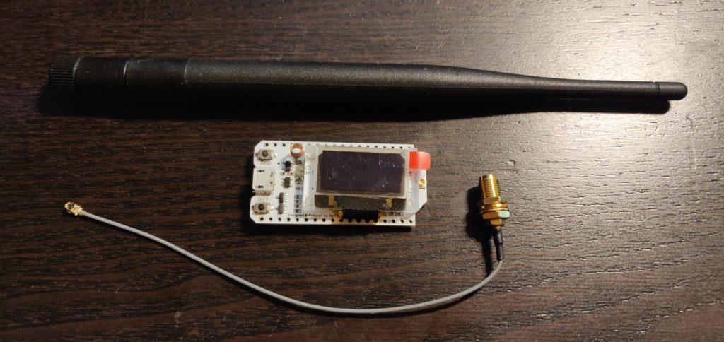
Last year I bought a couple of Heltec ESP32 boards fitted with the SX1276 LoRa radio chipset to explore what looked like an attractive alternative to cellular modems for getting sensor data from a sensor to a web application or database.
An organisation called The Things Network has built an interesting network, in which the infrastructure that provides radio coverage is completely provided, installed and maintained by the community of users, in exchange, they get to use it free of charge and critically, get to use everyone else’s access points (or Gateways as they are called).
And it is the Gateway that was my first step into this project, so the following information will get you up and running quickly and with minimal effort, by following a few steps where I and others have already validated that they work.
Here’s what you need. You can click the links below to buy the correct parts directly:
- A Windows, Linux or Mac computer,
- The Arduino Integrated Development Environment,
- A USB to micro USB cable,
- Either:
- A Heltec ESP32 LORA board, or
- A Wemos D1 Mini ESP8266 board and LoRa shield, or
- An already-built 8266 LoRa board.
- An 868MHz antenna (with cable to connect to the UFL connector on the board if you use the Heltec board)
- And, of course, access to the internet, via WiFi.
This page deals with the Heltec variant for now and I will add instructions for the 8266 one when it arrives here. I will assume that you have the Arduino IDE installed, if not, there are some great instructions here for Windows, Mac and Linux.
If you don’t already have it, you need the ESP32 core for Arduino that enables programming the Heltec (and lots of other) ESP32 boards. Open Arduino, click File, then Preferences.
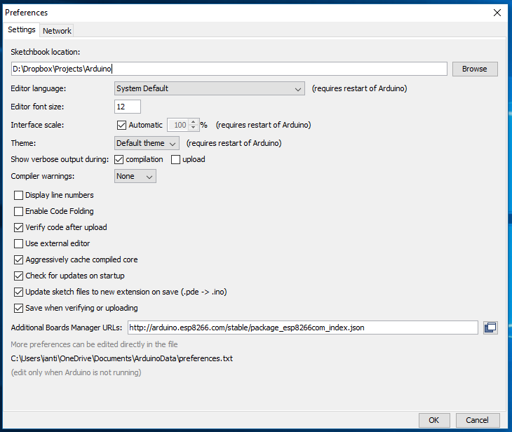
In the Additional Boards Manager URLs box, type:
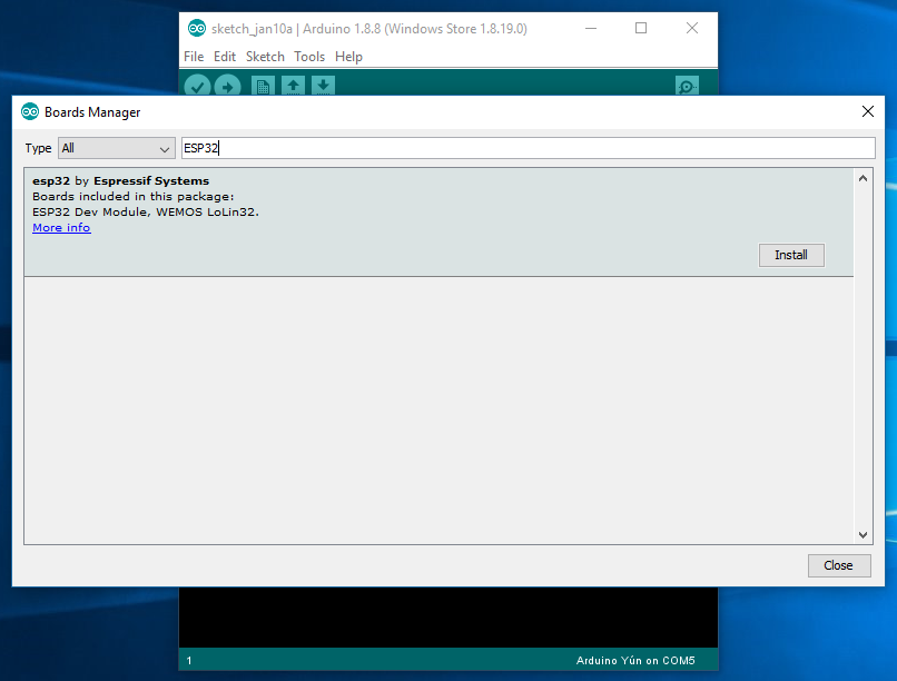
http://arduino.esp8266.com/stable/package_esp8266com_index.json,https://dl.espressif.com/dl/package_esp32_index.jsonThe two entries give you access to ESP32 and also the excellent ESP8266 in addition to the standard Arduino boards. Next, install the ESP32 through Boards Manager – click Tools, Board, Boards Manager and when it has finished updating its list type ‘ESP32’ in the search box, then install the ESP32 core.
Next is to get the CP2102 virtual comms port driver for your operating system if you don’t already have it. I got mine from SILABS here.
Comprehensive documentation is provided by Maarten Westenberg at his github page, I’ll list the bare minimum to correctly configure the gateway.
Now you need to get the package that runs the single channel LoRa gateway on the Heltec board, which you can download from this link. Normally at this point I would say to unzip the file into your Arduino Libraries folder, but in this case, just unzip it to your desktop, as it intentionally contains all the library files and sketch needed for the gateway. This is neat, since it means you won’t mess up your Arduino libraries by installing different versions and you’ll get a complete, working set in one go (almost) ready to compile.
Next, in Arduino, go back to File, Preferences and make a note of your current sketchbook folder so that you can restore it later (otherwise you’ll lose access to your original libraries and sketches) and then change it to match the folder on the desktop that you unzipped the gateway files to.
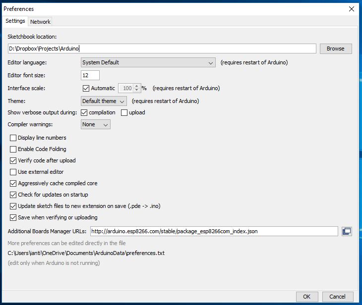
Close and restart the Arduino IDE.
Open the ESP-sc-gway.ino sketch in your Arduino sketchbook. You’ll see that a number of other files are also loaded as tabs actoss the top of the window.
Now edit the file called ESP-sc-gway.h in one of the tabs and make the following changes:
Change the Spreading Factor from SF9 to be SF7 by default.
#define _SPREADING SF7Change the pinout from 1 to 4.
#define _PIN_OUT 4Change the OLED type from 2 to 1.
#define OLED 2Find the Gateway Ident Definitions block and amend it, adding your own information – note that putting the correct location (lat and long) is important if you ever use the LoRa Mapper app on Android, or your Gateway will appear to be in Amsterdam! Similarly, choose an email address that you don’t mind being public (as it is visible via TTN).
// Gateway Ident definitions
#define _DESCRIPTION "ESP Gateway"	// Name of the gateway
#define _EMAIL "email@domain.com"	// Owner
#define _PLATFORM "ESP8266"
#define _LAT 52.0
#define _LON 5.0
#define _ALT 1				// Altitude
Next is the NTP block – here you need to set your time zone and preferred NTP server.
// ntp
// Please add daylight saving time to NTP_TIMEZONES when desired
#define NTP_TIMESERVER "uk.pool.ntp.org"   // Country and region specific
#define NTP_TIMEZONES	0    // How far is our Timezone from UTC (excl daylight saving/summer time)
#define SECS_IN_HOUR	3600
#define NTP_INTR 0  // Do NTP processing with interrupts or in loop();
Find the wpas block and edit it to place your WiFi SSID and password into the second line of the set (leave the first blank). If you have a second available access point, you may enter it in the next line below that (instead of ‘ape’ and ‘beer’).
wpas wpa[] = {
	{ "" , "" },		// Reserved for WiFi Manager
	{ "yourWifFiSSID", "yourWiFiPassword" },
	{ "ape", "beer" }
};
Make sure you save the file!
We are nearly there now. Select the board in the Arduino – it should be in the new ESP32 section and is called Heltec_WIFI_LoRa_32.
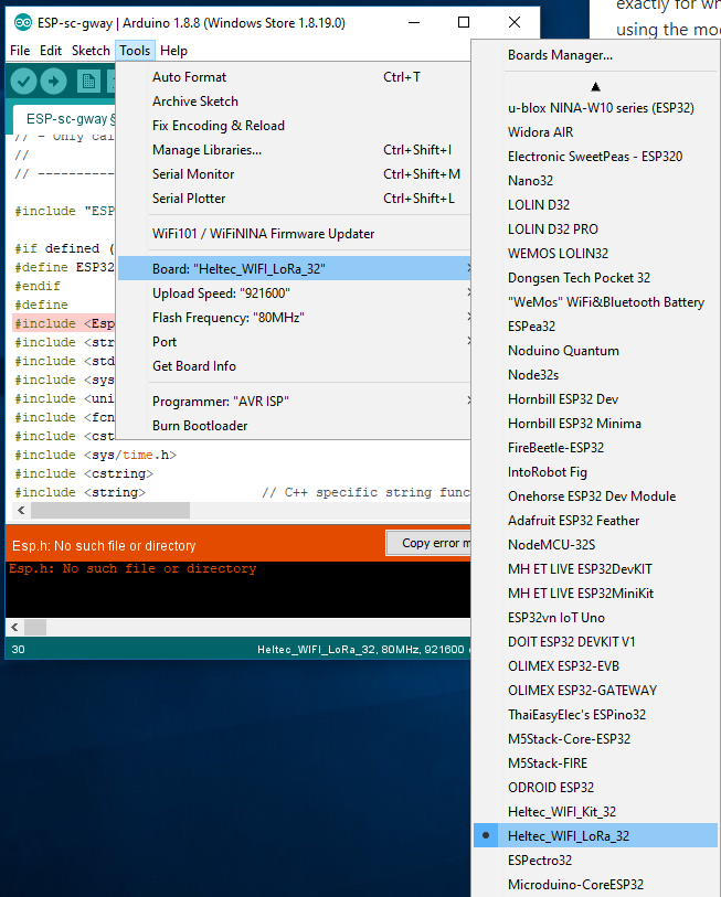
Select the correct USB port in Tools, Port (mine was USB6).
Open your serial console at 115200 baud. Compile the sketch (it should work first time as you have all the libraries already) and then upload it to the board. Assuming all went well, upload the code to your board.
Watch the serial console, you should see a number of messages, including one that says there’s a memory error:
M ERR:: readConfig, file=/gwayConfig.txt does not exist .. FormattingThis step takes a couple of minutes after which the device doesn’t look like it is working. Leave it a while. If all goes to plan, you should find a clean boot that looks like:
rst:0xc (SW_CPU_RESET),boot:0x17 (SPI_FAST_FLASH_BOOT)
configsip: 0, SPIWP:0xee
clk_drv:0x00,q_drv:0x00,d_drv:0x00,cs0_drv:0x00,hd_drv:0x00,wp_drv:0x00
mode:DIO, clock div:1
load:0x3fff0018,len:4
load:0x3fff001c,len:808
load:0x40078000,len:6084
load:0x40080000,len:6696
entry 0x400802e4
ESP32 defined, freq=868100000 EU868
ARDUINO_ARCH_ESP32 defined
SPIFFS init success
Assert=Do Asserts
debug=1
readConfig:: Starting
.SSID=	yourWiFiSSID
.PASS=	yourWiFiPassword
.CH=	0
.SF=	7
.FCNT=	0
.DEBUG=	1
.PDEBUG=64
.CAD=1
.HOP=0
.NODE=	0
.BOOTS=	2
.RESETS=	0
.WIFIS=	2
.VIEWS=	0
.REFR=	0
.REENTS=	0
.NTPETIM=	0
.NTPERR=	0
.NTPS=	0
.FILEREC=	0
.FILENO=	0
.FILENUM=	0
.EXPERT=	0
#

MAC: 24:0f:34:42:c6:e1, len=17
WlanConnect:: Init para 0
0:1:3. WiFi connect SSID=yourWiFiSSID, pass=yourWiFiPassword
A WlanStatus:: CONNECTED to ABS-ZERO-IOT
Host esp32-8256e0 WiFi Connected to ABS-ZERO-IOT on IP=192.168.0.6
Local UDP port=1700
Connection successful
Gateway ID: 240F34FFFF42C6E1, Listening at SF7 on 868.10 Mhz.
setupOta:: Started
Ready
IP address: 192.168.0.6
Time: Friday 00:01:09
Gateway configuration saved
WWW Server started on port 80
OLED_ADDR=0x3C
--------------------------------------
A readUdp:: NTP msg rcvd
Copy the Gateway ID, in the case above it was: 240F34FFFF42C6E1 – you need this to register the gateway on TTN.
Now open a browser and go to www.thethingsnetwork.org and if you haven’t already, register an account and then login. Click your name in the top right and in the drop down menu, click ‘Console‘.
Click Gateways and then in the blank screen that follows, click ‘register gateway‘.
Then in the next screen, click the check box that says ‘I’m using the legacy packet forwarder‘ and then paste the Gateway EUI you recorded before into the input field. Select the frequency band your module supports and choose the nearest router to your location. Here you also tell TTN where your node lives by clicking on the map.
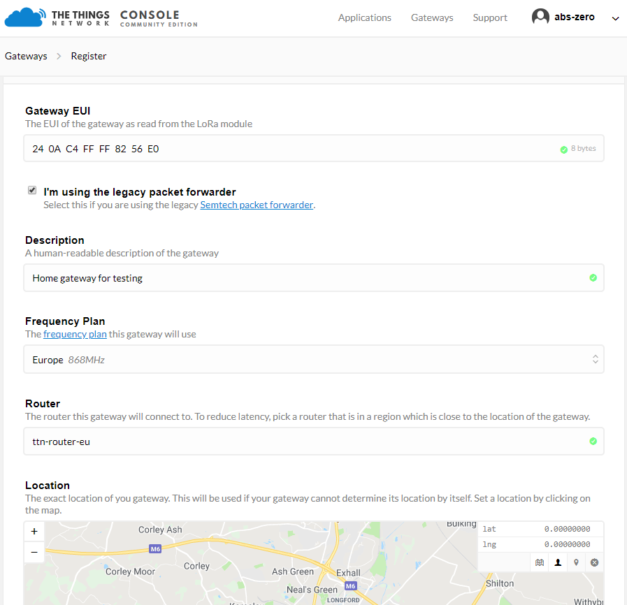
When everything is complete, click ‘Register Gateway’ button at the bottom and this will take you back to the status screen. Almost instantly, the gateway should show up as being online.
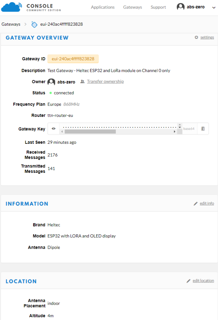
I have a few more notes to add to this page, coming soon…
Namely how to build a node using an Arduino ProMini, LoRa board, carrier PCB and antenna.
Alternative single channel gateway ready built
Need a WiFi hotspot to host the single channel gateway? Try this one, which can connect via ethernet or by adding a USB 4G modem, or this one, which has the modem, router and a battery already built, configured and ready to go.
![[Abs-Zero]](http://www.abs-zero.com/wordpress/wp-content/uploads/2013/11/abs-zero.jpg)