![[Abs-Zero]](https://www.abs-zero.com/wordpress/wp-content/uploads/2013/11/abs-zero.jpg)
Introduction
When I started building Meshcore repeaters, I quickly realised there are many hardware options and some are better than others. My main aim has been to build devices that can be put out in the field and then left untouched for a year at a time, if not more. No battery maintenance, no leaks or replacements, just (over the air) firmware updates.
Features
- nRF52840 ProMini selected for low power,
- Heltec RA-62 SX1262 radio selected for best performance,
- INA219 power monitor (enables charge current telemetry),
- TP4056 Solar charge controller – cheap and effective with great low-light performance – see bottom of page for more info.
- NCV301-2.8 Voltage Supervisor IC prevents brown-out freeze,
- Additional header provided for a BME280 or other i2c sensor,
- Programming compatible with ‘FakeTec’ board in the MeshCore/MeshTastic Web Flasher,
- Easy to solder,
- Much easier to build a full repeater correctly first time than Veroboard or manual wiring!
Specification
- 14mA current while receiving packets
- Suitable for Lithium Ion / Lithium Polymer (LiIon/LiPo) 1S packs with nominal 3.7V cells)
- Charges the battery pack at up to 750mA
- Solar input Voltage must not exceed 8V
- Tested with 1S1P to 1S5P Lithium packs of capacities 3,000mAh to 15,000mAh, minimum capacity 1,000mAh (for charge current safety).
Design Rationale
On the electronics side, as I defaulted to including extra functionality as standard, such as high current charging, charge current monitoring and addition of other i2c sensors, wiring became more and more of an issue. Keeping things compact, while still reliable is important and the scope to mis-wire a connection often means the whole repeater won’t even boot. Because this wasn’t my first repeater build, I’d learned already about what happens when a repeater runs low on power (most will brown out and crash until manually reset).
This design overcomes that by including a Voltage Supervisor IC that detects when the supply Voltage dips below 2.8V and holds the ProMicro in reset until the Voltage recovers enough to safely resume operation. A clean reboot is then assured, though depending on the battery quality, the next transmit might re-trigger the reset and hold the device offline (until the solar charger catches up). I have tested this extensively and deliberately covered up the solar panel on my test repeater to verify it recovers reliably by itself.
To that end, I designed my own enclosures and my own Printed Circuit Boards (PCBs). I’ve designed these to be as easy to build as possible, so 1207 size surface mount components are used, with the exception of the Voltage supervisor. Everything fits within the board outline and the mounting holes are kept clear so you can screw it into a box if that’s how you want to build it.
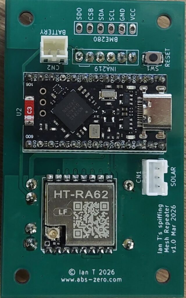
Here you can find the PCB and its assembly instructions – if I’ve given you a board, this is how to put it together. The photo below shows the completed assembly.
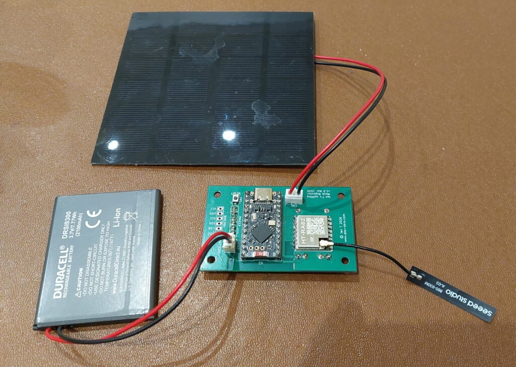
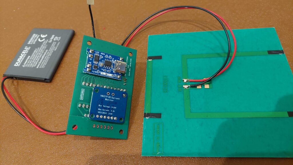
A INA219 board is soldered to the other side (hidden) to monitor power, but this is optional if you don’t want to use one:
Assembly
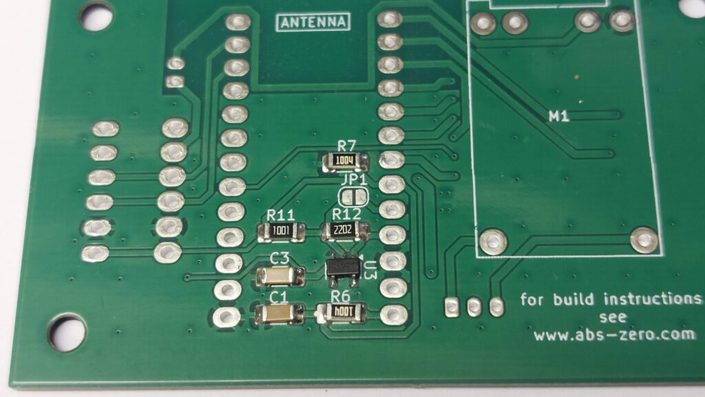
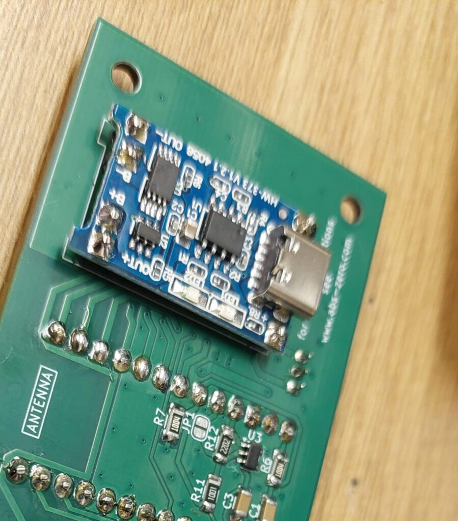
Start on the back of the board by soldering the surface mount components – I suggest starting with the 5-pin Voltage supervisor IC, as it’s the smallest; you will need to use fine tweezers for these, tack solder one leg of each component while holding it in the correct position with the tweezers and then solder its remaining pins before finishing the first one. Leave the jumper pads open, they’re used if the supervisor isn’t fitted (contact me if you go this route for instructions) Component values are as below:
- R6 and R7 are 1M,
- R11 is 1k,
- R12 is 22k,
- C3 and C1 are both 100nF
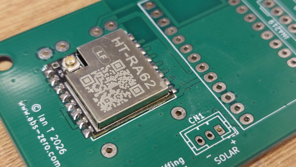
Next, working on the front of the board, solder the radio module onto its pads. Same technique, hold it in place while soldering one corner pad, solder the opposite corner pad and then the rest once you have confirmed it is correctly aligned. If after soldering the first pad it isn’t correct, you can simply melt the solder on that one pad and re-align.
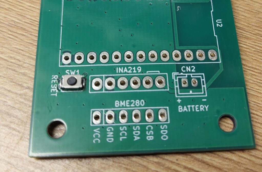
Still on the front side of the board, solder the reset button (not essential you fit one, but the pads are there). Again, use tweezers, same technique as for the other surface mount components. These pads are a bit smaller, so take care to align it perfectly.
The next step is to add the nRF ProMini board. I’d strongly advise installing the OTAFIX bootloader from oltaco before fitting. Fit it to the front of the PCB as shown, taking care to ensure the red ceramic ‘C3’ antenna component is at the top of the board. Check the reverse of the board for the word ‘ANTENNA’ in the same position. This is your Bluetooth antenna for later firmware upgrades etc.
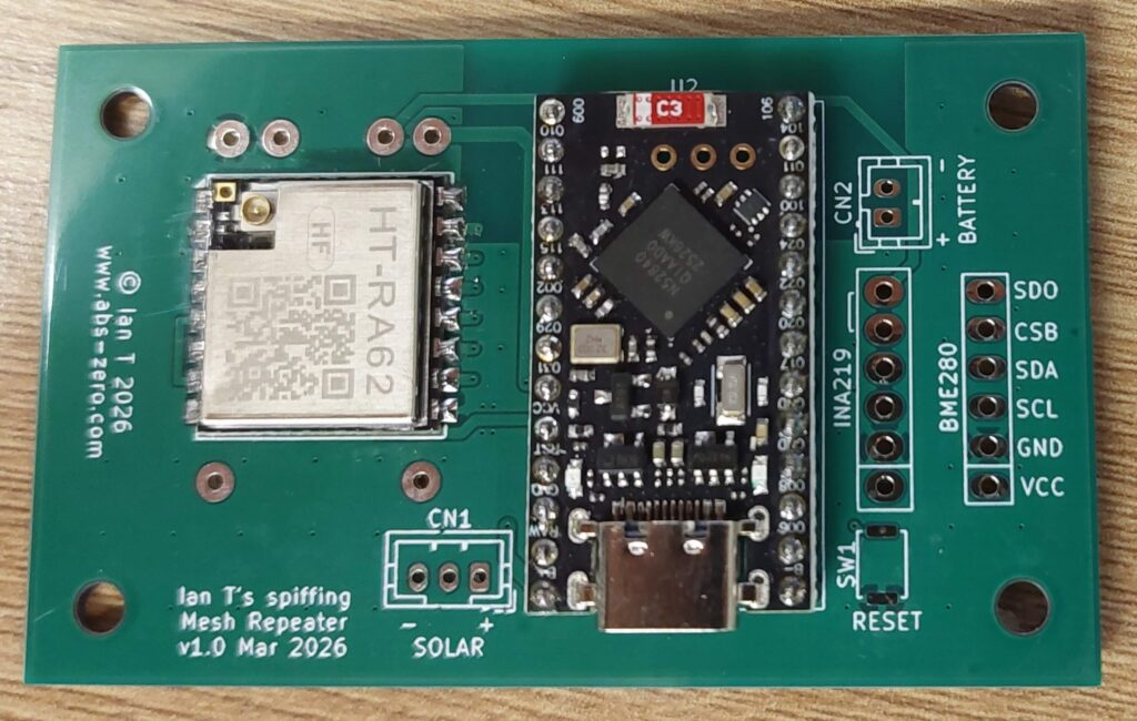
Now install the connectors for solar input and battery to the board. I deliberately used a 3-pin connector for the solar input so that it isn’t possible to connect the battery and solar to the wrong connectors. Note their alignment – the battery connector has its locating keyway oriented inwards and the solar panel has it facing outwards. Pinouts are as follows:
- Solar: Pin 1 = Positive wire from the solar panel, Pin 2 = not used, Pin 3 = Negative wire from the solar panel
- Battery: Pin 1 = positive wire from the battery, Pin 2 = Negative wire from the battery
Now fit the TP4056 module to the back of the board (the opposite side to the radio). Ensure that its components face you as you solder, otherwise it will have its polarity reversed.
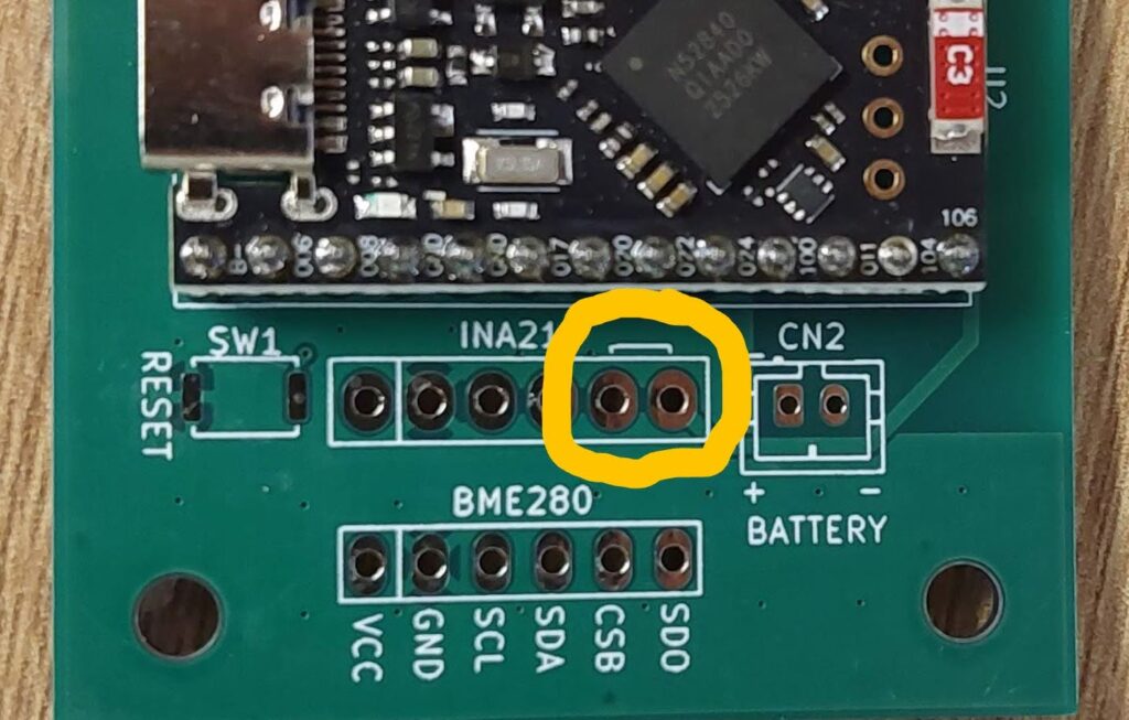
Next is the INA219 – it is optional, so if you decide NOT to fit it, you must bridge these two pins:
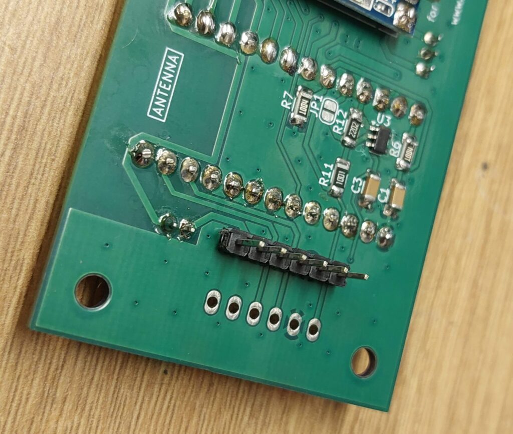
If fitting the INA219, it is fitted to the rear of the board, with its components FACING the board, so first fit it’s header.
Then add the INA219 module. I put a couple of layers of Kapton tape over the components , but this isn’t necessary, just ensure that there is at least 2mm of clear gap between the components on the INA219 module and the nearest pin or component on the main board.
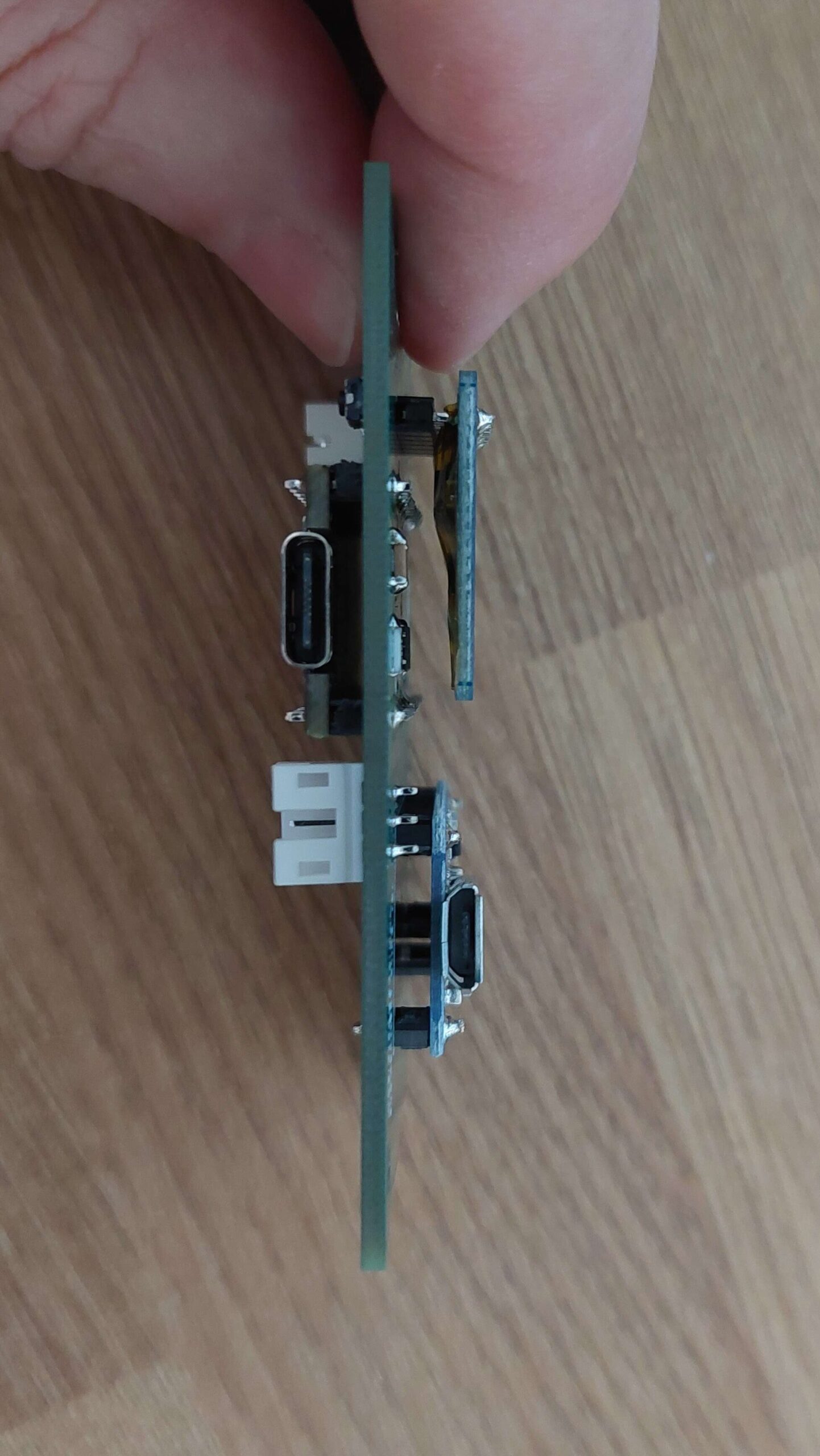
Assembly is now complete. Ensure that an antenna is connected to the LoRa radio module as it can destroy itself if allowed to transmit while one is not fitted. Program the board with MeshCore repeater firmware using the MeshCore Flasher. When doing so, make sure to select the ‘ProMicro nRF (faketec)‘ option in the Flasher.
Any issues, contact me via Discord in the MeshCore.IO discord server. If you’re not already a member, click here: https://discord.gg/Q3PFnVCKk
Why the TP4056 charger?
This is something I’ve been asked a few times. Some will tell you that the TP4056 is unsafe when connected to loads that are switched on when charging. The safety aspect is worth considering really carefully, so I did – it relates to the TP4056 not being able to detect the end of charging and therefore continuing to pump a charge current into an already fully charged battery. In the case of my mesh repeater board, I can be certain that the current drawn dips low enough when not transmitting for that end-of-charge detection to take place and this can be verified simply by watching the behaviour of the board – when charge is complete (usually by about 0800 in summer), the board will then show no charging at all for the rest of the day on a typically large battery pack. This clearly shows that charge completion is detected within the TP4056 and it is then sat waiting for the pack Voltage to fall below the ‘start charging again’ threshold. So it’s safe; there’s no benefit at all from insisting on a ‘power path’ design that bypasses the charger to supply power directly to the repeater when charging.
The other reasons for choosing this device are far simpler, it’s very effective indeed when faced with overcast conditions. Many MPPT type chargers use boost converters that don’t even start up before the TP4056 starts providing a small current to the battery. In my previous testing, I found that this overcast condition (typical through winter) meant that the charger was able to harvest small amounts of energy in bad conditions and is still able to really gulp when the sun shines for short periods. I’ve used 165x165mm 6V panels with these boards and a 10,000mAh Lithium-Ion battery home-made from reclaimed laptop 18650 cells that has gone through the winter and never went below 50% charge even when faced with the longest (January/February 2025) spells of dull weather.